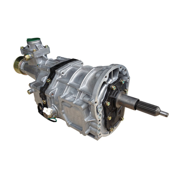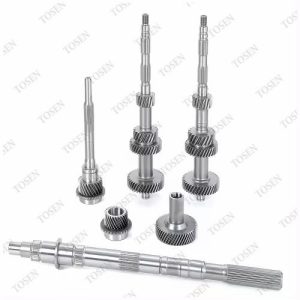
To compare a manual gearbox input shaft before ordering, record the clutch spline count and outside diameter, the smooth pilot-journal diameter, and the shaft projection from a named mounting face. Add the relevant contact lengths and a labelled side-view sketch. A spline count or a length without a reference face cannot establish that two input interfaces match.
Measure the removed gearbox in a safely supported, stationary condition under the workshop handling procedure. Keep the gearbox identification, clutch and pilot-bearing arrangement with the measurements; the dimensions help identify a candidate, while the applicable drawings and service information determine the required fit.
Record the clutch spline and pilot journal separately
The toothed portion mates with the clutch-disc hub; the smooth tip, where the design uses one, mates with the pilot bearing or bushing. The larger front bearing-retainer sleeve is another feature again. Mark these separately on a photograph so that a supplier cannot mistake a retainer diameter for a pilot diameter.
- Count the clutch splines. Mark a starting tooth and count once around, then repeat the count. Record any unusual missing or interrupted feature rather than interpreting it as a standard count from a photograph.
- Record spline outside diameter and usable length. Identify the outside diameter across the tooth crests and the axial portion intended to engage the hub. Do not include a lead-in chamfer or damaged section as usable engagement. A caliper reading is an identification measurement; it does not establish the full tooth profile, pitch or fit.
- Measure the smooth pilot journal. Identify the intended bearing-contact region, away from a chamfer, shoulder or worn groove. Record its diameter and axial contact length separately. Use the measuring instrument and inspection method appropriate to the part specification; where wear is suspected, a single reading is insufficient.
- Describe the surface condition. Note worn steps, scoring, corrosion, damaged teeth or visible twist. Distinguish a measured worn diameter from the nominal dimension on the replacement drawing.
Manufacturer input-shaft tables commonly separate these features: the TKO parts catalogue lists spline count, spline outside diameter, pilot outside diameter and length for its variants. Use that separation when preparing your record, while taking actual nominal dimensions and acceptance limits from the drawing for the gearbox being ordered.
Measure stick-out from a clearly named mounting face
Stick-out is an axial projection from a declared face to a declared endpoint. The front mounting face of a bare transmission case and the engine-mating face of an attached bellhousing are different planes. A loose shaft’s overall length includes portions inside the gearbox and is not the same measurement.
- Name the assembly condition. Record whether the bellhousing and any adapter are fitted. On the sketch, label A as the transmission-case mounting plane, B as the engine-mating plane of the fitted housing or adapter, and C as the shaft-tip endpoint. For an integral housing, identify the actual face shown on the applicable drawing.
- Choose the dimension to compare. A-to-C and B-to-C describe different projections. Use the one specified by the supplier’s drawing, naming both endpoints. Also mark the beginning and end of the useful spline and pilot contact regions if their axial positions are needed.
- Transfer the reference plane accurately. A straightedge or suitable bridge can represent a mounting plane for an axial depth or length measurement. Keep it seated on the intended clean, undamaged reference surface, not on the protruding retainer or an unrelated casting boss. Record and account for any bridge offset.
- Record units and repeat the measurement. Keep the original unit and instrument resolution with the result. Repeat from the same plane; compare against the same endpoints on the offered-unit drawing before converting or rounding anything.
The TKX service manual’s dimension key, for example, defines input-shaft length from the transmission front face. That is a definition for its drawing, not a universal instruction to measure from whichever face is easiest to reach. An adapter changes the mating-plane relationship even when the shaft itself is unchanged.
Put the measurements on one labelled comparison sketch
Use one side-view sketch and an end-view photograph to identify the features, then place the old-unit measurements beside the offered drawing values. Label the record as a blank comparison until actual measurements and references have been entered. Do not use a product photograph as a scale drawing.
| Feature on the sketch | Removed gearbox | Offered gearbox / drawing |
|---|---|---|
| Gearbox identity and assembly condition | Enter tag/reference; housing and adapter fitted or removed. | Enter exact part/variant and drawing revision. |
| Spline count and profile reference | Enter counted teeth; note damage or interrupted features. | Enter specified count and full profile reference where available. |
| Spline outside diameter and useful axial length | Enter measured values, units and contact endpoints. | Enter nominal dimensions, endpoints and applicable limits. |
| Smooth pilot diameter and contact length | Enter readings and describe wear or scoring. | Enter pilot specification and matching bearing arrangement. |
| A-to-C or B-to-C projection | Enter value and explicitly name the starting face and tip endpoint. | Enter the corresponding dimension from the same reference plane. |
| Separate retainer / housing details | Enter relevant sleeve, register, housing and adapter identity. | Enter corresponding interface dimensions and configuration. |
Keep the scale close to the feature in the photograph and mark the measurement locations on the sketch. The photograph explains which surface was measured; the instrument reading supplies the value. Ask for the same labelled dimensions on the proposed gearbox, including any unresolved tolerance or engagement requirement, so the reply can be compared line by line.
Use the mismatch to choose the next check
Use the disagreement to identify the next question, rather than averaging dimensions or assuming the old unit defines the correct new-part limit. The following are illustrative comparison outcomes, not vehicle-specific fit approvals:
- Same spline count, different spline diameter or profile. The clutch interface remains unmatched. Resolve the exact input-shaft and clutch-disc specification before ordering.
- Matching clutch splines, different smooth pilot. Check the shaft variant and the specified pilot bearing or bushing. Chevrolet Performance’s L8T instructions, part 19433751, list different pilot-bearing choices for long and short input-shaft arrangements; that example does not select a bearing for another engine.
- Different length, unclear reference face. Obtain the missing datum and assembly condition first. Two otherwise correct figures can describe different planes; a housing or adapter must not be silently ignored.
- Matching recorded input dimensions, but uncertain installation. Clutch centering, pilot support, housing alignment and other assembly interfaces still require their own checks. Gearbox mounts, output connection, ratios and controls are outside this input-shaft measurement record.
A gearbox that will not mate needs diagnosis under the applicable fitting instructions. Do not treat these measurements as permission to pull the assemblies together with bolts, shorten the shaft or improvise a spacer. Resolve the correct variant and complete mating arrangement before installation.
Frequently Asked Questions
Can a clear photograph replace instrument measurements?
It can identify features and document damage, but perspective and scale placement limit dimensional accuracy. Use labelled photographs alongside instrument readings and the applicable drawing, especially for bearing fits or closely matched spline features.
Should the replacement drawing match every worn dimension on the old shaft?
No. An old part can help establish identity while wear changes its measured surfaces. Resolve the replacement’s nominal dimensions and acceptance limits from the correct part specification instead of copying a worn reading as the target.
Send a comparison that names every measured surface
A useful input-shaft comparison identifies the clutch spline, smooth pilot and axial reference face separately. If you are comparing manual transmissions, keep the gearbox tag, labelled sketch and retained clutch or pilot-bearing details together with the enquiry.
Use the TOSEN AUTO catalogue with that comparison to prepare questions about the exact gearbox variant and any unresolved mating dimensions.