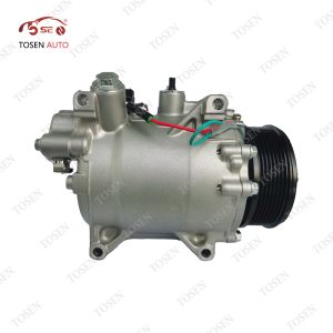
A/C compressor mounting-ear alignment starts with the correct bracket, contact faces and specified hardware. Have the qualified technician establish the intended seating arrangement before final fastening. Using bolt torque to pull an unexplained mismatch into place can load the housing or its mounts.
A visible gap needs interpretation against the exact vehicle and compressor instructions. It is not automatically a defect, and it is not automatically safe to close. Identify what should contact, which sleeves or spacers belong in the assembly, and what remains unexplained before proceeding.
Why mounting holes can line up while the housing is still loaded
A bolt passing through a mounting ear shows that the holes overlap. It does not establish the intended contact between the compressor, bracket and any specified mounting components. If that stack is wrong, tightening can impose load while drawing the parts together. Incorrect fastening can also damage the ears.
GM service bulletin PI0767B provides a specific example: on its named 2012–2013 V6 Chevrolet and GMC applications, an assembly torque condition could load the compressor shaft. The bulletin calls for application-specific mounting and tightening information. It illustrates why seating matters; it does not supply a repair method for every compressor.
Compare the bracket, mounting faces and specified hardware
Compare the actual replacement and the vehicle's mounting arrangement with the parts information and service procedure. A similar housing shape or a shared vehicle model name is insufficient to settle every interface.
| Interface | What to compare | Question to resolve |
|---|---|---|
| Application and compressor identity | Vehicle/engine variant, old-unit reference and the specific offered replacement | Is this the intended compressor and mounting arrangement? |
| Bracket and mounting ears | Contact pattern, hole positions and visible damage or obstruction | Can the specified contacts be established without an unexplained mismatch? |
| Mounting faces | The surfaces named by the procedure and their observed condition | Is an apparent gap a wrong contact, obstruction or a service-defined arrangement? |
| Sleeves, spacers or locating parts | Presence, reference and position of any components shown for this application | Is the mounting stack complete and correctly identified? |
| Bolts and associated hardware | The specified fasteners, washers and arrangement where required | Does the hardware match the exact procedure rather than an assumed substitute? |
| Pulley, ports and connections | The separate application-specific interfaces | Does the rest of the compressor match after the mounting question is resolved? |
Some mounting arrangements use components that locate or accommodate the assembly; others differ. Treat sleeves and spacers as conditional parts of the actual design. This checklist does not establish that every compressor has them, that an old sleeve should be transferred, or that a sleeve should be pressed into a new position.
Decide what an observed gap actually means
- Identify the intended contact arrangement. Locate the correct vehicle and compressor instructions. Ask which faces should contact and how any specified locating or take-up components function before interpreting the gap.
- Record the observation state and location. Distinguish an observation made during positioning from one made at the service procedure's specified inspection stage. Mark the particular ear or bracket interface and retain the units of any measurement.
- Compare the complete mounting stack. Have the technician check the identified bracket, faces and specified hardware. A missing component, a wrong interface or apparent damage needs explanation before final fastening.
- Pause when the mismatch remains unexplained. Return the location-labelled observations and part references for clarification. Do not use a torque value borrowed from another compressor to decide that an unfamiliar gap is acceptable.
There is no single gap number or universal 'all faces flush' rule for this guide. Follow the contact and clearance requirements for the actual mounting design, including any service-defined take-up. Do not assume that a designed clearance and an unexpected offset are the same condition.
Sleeve repositioning, added washers, grinding a face or changing the bracket are repair decisions that require the correct procedure. A generic installation tip cannot authorize them. Once the arrangement is understood, the qualified technician follows the specified support, tightening sequence and torque for that application.
Record the mismatch and the checks still needed
A useful clarification request shows which parts were compared, where the mismatch appears and the state in which it was observed. Use photographs and measurements of the actual offered or installed components.
- Identify both sides of the interface. Include vehicle/engine details, compressor reference and the bracket or mounting-parts references available for that application.
- Show the whole arrangement and the individual contact. Provide a wider view for orientation and a labelled close view of the relevant ear, face and specified sleeve or spacer. Record visible condition without treating a photograph as proof that hidden damage is absent.
- Attach the observation conditions. State the inspection stage, location and units of any gap reading. Include the applicable service-data reference and the exact question the technician cannot resolve.
- Keep the completion checks separate. Record the workshop's resolution and the service-specified fastening checks. Confirm the required pulley/belt alignment checks separately; a bolt fitting through its hole cannot establish belt alignment.
Documented OEM belt-noise investigations also distinguish compressor mounting alignment from other drive-system causes. A mounting check therefore does not replace the complete diagnosis or the prescribed final inspection.
If a different unit is needed, compare replacement A/C compressors using the recorded identifiers and interface photographs. Confirm the actual offered configuration and supplied mounting components before choosing it.
Frequently Asked Questions
Can I reuse the torque value from a similar compressor?
Do not transfer it by appearance or vehicle family. Use the specified mounting fasteners, tightening sequence and torque for the exact application; the correct value depends on the actual assembly.
Does belt noise prove that a mounting ear is damaged?
No. OEM diagnostic cases include mounting alignment among possible causes, while other drive-system conditions can produce similar symptoms. Have the qualified workshop diagnose the actual condition rather than ordering a compressor from the noise alone.
Resolve the mounting arrangement before final fastening
The mounting check is complete when the intended contacts, hardware and service-defined clearances are understood and the qualified technician can follow the exact procedure. Keep any unresolved mismatch visible in the workshop record.
Use this interface record when discussing a replacement from TOSEN AUTO's catalogue, and clarify missing mounting details before accepting the proposed unit.