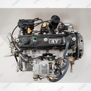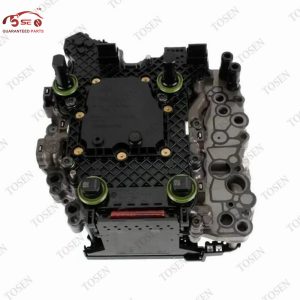
DSG basic settings after mechatronic replacement are not one universal reset. The correct function depends on the installed transmission family, controller generation, software state and repair scope. Start by identifying the exact gearbox and replacement unit, then follow the current guided routine for that controller.
A successful installation may still need coding, stationary calibration or later road learning. If the routine will not start or complete, save the status and diagnose the unmet condition before blaming the replacement or repeating the same command.
Identify the Exact DSG Family Before Opening Basic Settings
| Item | Description |
|---|---|
| Gearbox family | The transmission architecture and code group, such as 0AM/0CW DQ200, 02E/0D9 DQ250, or 0BH/0BT/0GC DQ500/DQ381. |
| Controller identity | The complete hardware, software and diagnostic identification reported by the installed transmission controller. |
| Applicable routine | The current guided function or service procedure for that exact family, controller generation and repair. |
| Family context | Start with | Procedure implication | Do not assume |
|---|---|---|---|
| DQ200 (0AM/0CW) | Full mechatronic label, gearbox code and diagnostic ID | Older 0AM and MQB-era 0CW contexts can expose different software and functions | One DQ200 channel list covers both |
| DQ250 (02E/0D9) | Installed code, controller version and current guided functions | Traditional measured-block and later controller implementations must be matched correctly | Any six-speed DSG follows the same screen sequence |
| DQ500/DQ381 (0BH/0BT/0GC) | UDS controller ID, gearbox code and visible status fields | The tool may present named functions and abort-status data | A routine from DQ200 or DQ250 transfers across |
| Another DSG family | Vehicle-specific repair information | Stop and identify the exact application before proceeding | A familiar DSG label is enough |
Photograph the transmission and mechatronic labels before removal, save the original scan, and compare them with the replacement identification after installation. Use the VIN and application lookup to support those physical records, especially when earlier repairs may have changed the installed unit.
Separate Basic Settings From Programming, Coding and Road Adaptation
Describe the required job by its result, not by the word “programming.” A replacement can contain suitable operating software and still need coding or basic settings. A completed stationary routine can also leave a family-specific road-learning task. Volkswagen's NHTSA-hosted 02E work instruction lists coding, basic measurement and basic calibration as separate guided functions, which is a useful example of these boundaries.
| Operation | What it changes | When it may apply | Evidence to retain |
|---|---|---|---|
| Programming or flashing | Operating software or calibration | The replacement needs suitable software for the application | Hardware/software identification and write result |
| Coding or configuration | Vehicle or equipment configuration | The controller must be configured for the vehicle | Coding before and after, plus supported function used |
| Basic settings | Reference positions or controller initialization under defined conditions | After specified repair or replacement work | Function name, conditions, final status and faults |
| Road adaptation | Learned behavior under a defined drive routine | When the exact service procedure requires it after stationary work | Drive conditions, final scan and observed shift behavior |
Write the remaining work in one sentence
Example: software loaded; coding verified; stationary basic settings pending; road learning required after successful completion.
Do not accept “plug and play” unless the supplier and installer list what was completed and what remains.
Check Every Prerequisite Before You Start
Use the prerequisite list shown by the current repair information or guided function for the exact controller. As one scoped example, Volkswagen Tech Tip 37-09-03 requires an operating-temperature 02E, clear engine and transmission faults, Park, idle and a minimum running time before its basic-settings route. Those values belong to the listed applications; they are not a universal DSG specification.
- Confirm the gearbox code, complete mechatronic or TCU identity, and installed software before selecting the function.
- Save the full fault scan. Resolve faults that the applicable procedure does not permit, rather than clearing them without diagnosis.
- Verify the specified fluid type, level and temperature for this transmission and repair.
- Set the selector, parking brake, foot brake, engine state and other vehicle conditions exactly as the guided function requires.
- Provide stable electrical power and use a diagnostic tool that supports the exact controller and named function.
- Review installation details: connectors, seals, transferred parts, hydraulic work and any family-specific mechanical position checks.
Stop when identity, software or installation is uncertain. A communication response only proves that the tool can reach the controller; it does not establish correct part fitment, hydraulic condition or readiness for calibration.
Use the Guided Routine for the Exact Controller
Open the controller only after the family and prerequisites are settled. Prefer the current factory guided function or a documented tool route for that exact controller. Do not substitute a channel number copied from another gearbox or older software version.
- Record the controller identification, installed unit label and starting fault scan under the same job number.
- Select the named basic-setting or calibration function for that controller and read the tool's prerequisite message before starting.
- Display available main status, sub-status, clutch or selector status, and abort information so a failure produces useful data.
- Run the function without changing brake, selector, engine state, power supply or other required conditions.
- Wait for the tool's final status, then follow the exact ignition-cycle, fault-scan and road-learning instructions for that family.
- Keep the vehicle secured and the work area clear while the transmission operates actuators.
- Do not interpret normal actuator noise without the tool status and applicable service information.
- Do not choose a broad “reset all adaptations” command unless the exact repair procedure calls for it.
- Save screenshots or a diagnostic report showing the selected function and final result.
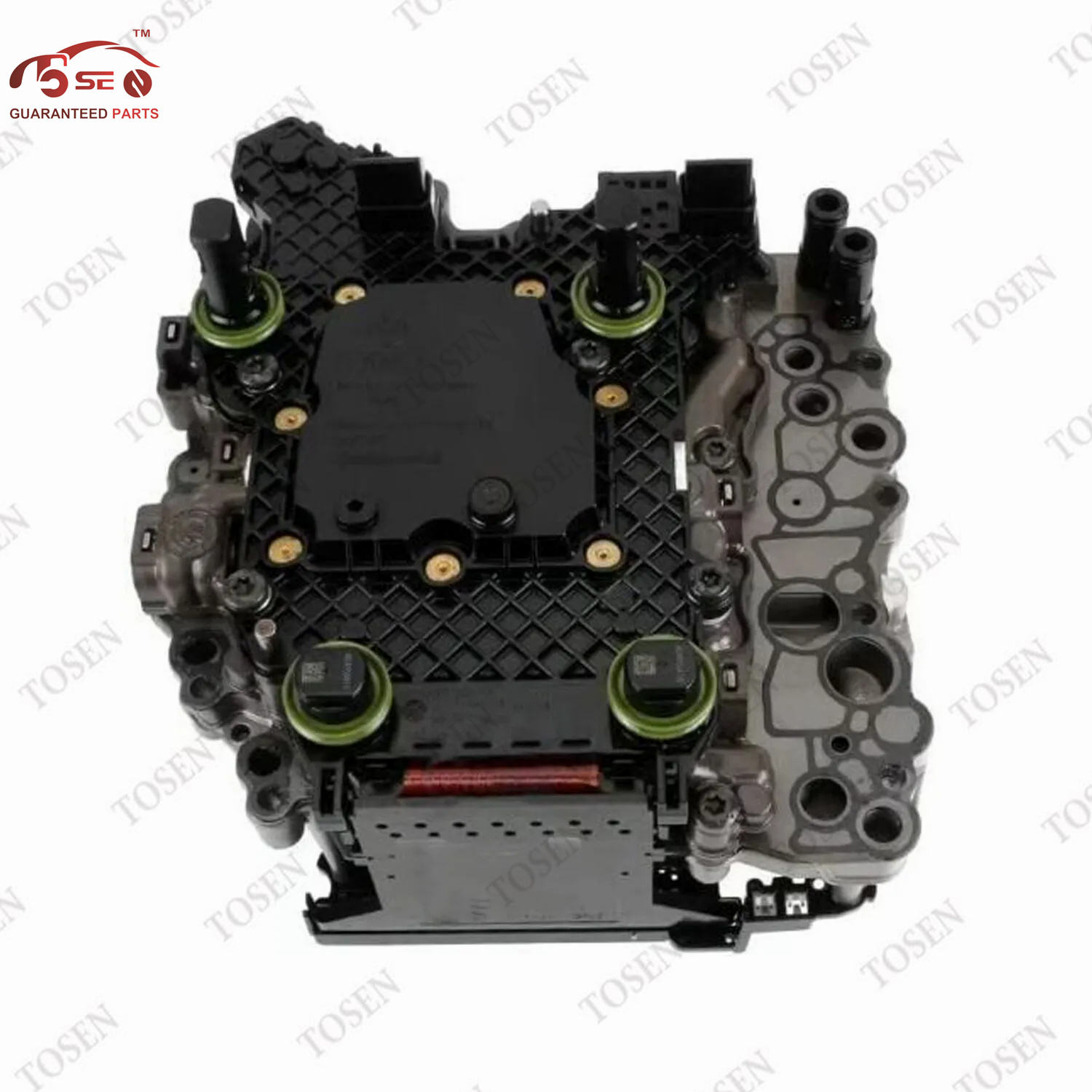
The parts plan should match this route. A DQ500 0BH Transmission Mechatronic Unit is one current commercial example, but its product label cannot determine vehicle fitment, coding or the guided function. The workshop must still match the installed identity and current repair information.
Read Completion Status Before Moving the Car
Completion is the combination of the tool's final status and the required follow-up for that transmission. Save the result before clearing faults or closing the job. A blank error memory by itself does not show which function ran or whether later road learning remains.
| Observed result | Meaning | Next action |
|---|---|---|
| Finished successfully | The selected stationary function completed under the recorded conditions | Perform the required ignition cycle, scan, gear-selection check and exact-family road procedure |
| Aborted with status detail | The controller stopped for a recorded reason | Save the detail and follow the failure branch before retrying |
| Conditions not correct | One or more start conditions are unmet or misread | Compare live values and vehicle state with the applicable prerequisite list |
| Function unavailable or unsupported | The chosen tool, controller or route may not match | Reconfirm controller generation, software, tool coverage and current repair information |
| Completed but symptoms remain | Calibration did not resolve the underlying concern | Return to diagnosis; inspect software, installation, hydraulics, clutch and mechanical condition as applicable |
For broader controller and assembly context, read DSG, CVT and Torque Converters: Transmission Control Units (TCU) Explained. Use that overview to align parts language, then return to the current procedure for the installed gearbox.
Diagnose an Aborted Basic Setting
Treat an abort as diagnostic information. Save the main status, sub-status, live values and fault codes while the failed condition is still present. Then move from the least invasive explanation to the more expensive one. Repeating the same function without changing a condition rarely adds useful information.
- Capture the failure — save the selected function, controller ID, abort text or code, temperatures, voltage and fault scan.
- Correct start conditions — compare selector, brakes, engine state, fluid, temperature and electrical supply with the exact procedure.
- Reconcile identity and software — confirm the replacement hardware, coding, software and application match the installed gearbox and vehicle.
- Review installation and hydraulics — inspect connectors, seals, transferred parts, fluid work, actuators and family-specific mechanical alignment.
- Diagnose remaining hardware or mechanical faults — use live values and the repair information; do not condemn the replacement solely because the routine failed.
- Did the failure begin before or after the replacement, programming or coding work?
- Does the new controller report the expected hardware and software identification?
- Can the tool show which clutch, selector, pressure or position stage did not complete?
- Are there power, communication, fluid, hydraulic, clutch or gearbox faults that calibration cannot repair?
- Has a different supported tool or current factory guided plan confirmed the same failure?
Stop the vehicle-side process when a consequential installation or hydraulic issue is unresolved. Preserve the original unit and records until the replacement has completed the required commissioning and the workshop has accepted the result.
Hand Off the Vehicle With a Usable Record
A useful handoff lets another technician understand what was installed, what the controller received, which guided function ran and what still needs attention. Keep the record with the invoice and warranty terms rather than relying on “adapted” or “ready” as the whole description.
- VIN/application, gearbox code and photographs of the original and replacement labels.
- Controller hardware/software identification and stated supply condition: blank, loaded, cloned, repaired original or another defined state.
- Pre-repair and post-repair fault scans with the basic-setting function and final status.
- Prerequisite values or conditions required by the exact procedure.
- Any required ignition cycle, coding, road adaptation and final gear-selection or shift-quality result.
- Unresolved faults, stop conditions, responsible party and written warranty or return steps.
Use parts pages after the job is defined
Browse Transmission Control Units only after the installed family, supplied scope and remaining software work are clear.
Send the same unit-linked record when asking a supplier for fitment or warranty support.
Frequently Asked Questions
Do all DSG transmissions use the same basic-settings procedure?
No. DQ200, DQ250, DQ381, DQ500 and other families can expose different functions, conditions and status values. Identify the installed gearbox and controller, then use current repair information and a supported tool for that exact application.
Does a pre-programmed mechatronic still need basic settings?
It can. Pre-programmed describes software preparation, not every vehicle-side task. Ask the supplier which software or data is present, and ask the installer which coding, basic settings, security-related work or road learning remains.
Can basic settings fix a faulty mechatronic?
Basic settings initialize or calibrate supported controller functions; they do not repair incompatible hardware, incorrect installation, hydraulic leakage, worn clutches or internal gearbox damage. If the routine aborts or symptoms remain, return to diagnosis.
Why does the diagnostic tool say conditions are not correct?
A required value or vehicle state may be outside the procedure's limits, or the selected function may not match the controller. Save the live values and status, then compare fluid, temperature, faults, selector, brakes, engine state, voltage and tool coverage with the exact procedure.
Is a road test always required after basic settings?
Follow the exact family procedure. Some workflows include a defined road-learning stage after the stationary function, while others specify different follow-up checks. Do not invent a generic drive cycle or move the vehicle before the stationary result and gear-selection checks are complete.
What should I send a supplier if the setup fails?
Send the VIN/application, gearbox code, old and new unit labels, controller hardware/software identification, full fault scans, the exact guided function, abort status, prerequisite values, installation notes and work already completed. Keep the original unit until the case is resolved.
Record the Result Before You Release the Vehicle
Choose the basic-settings route only after the installed DSG family, controller identity, software state and repair scope are clear. Meet the exact prerequisites, save the final status, complete the specified follow-up and diagnose any abort before another reset or part order.
Review the matching TOSEN AUTO transmission-control option. Send the VIN, gearbox code, old-unit label, replacement scope and commissioning record. Use those details to confirm the part and the workshop work that remains; do not rely on a DSG family name alone.