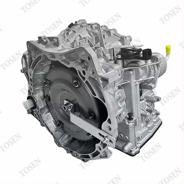
The RE0F10A is the identification carried in Nissan applications for the JF011E continuously variable transmission family, a Jatco CVT fitted to Dodge, Mitsubishi and Nissan vehicles in which a steel belt runs between two variable-width pulleys to deliver stepless ratio changes. In this architecture the hydraulic pressure and the electronic control vary pulley width together, so the whole transmission operates as one engineered system rather than a set of separate parts. Overheating in such a unit announces itself through observable behavior long before any internal conclusion can be drawn: a temperature warning on the dash, power that fades under sustained load, or engagement characteristics that differ between a cold start and fully warm running. This guide explains why heat deserves attention in a belt-and-pulley CVT, which early signs are worth recording, how to verify the cause before any part is ordered, and how to specify the correct replacement assembly when workshop findings justify one.
Why Heat Deserves Attention in a Belt-and-Pulley CVT
A conventional automatic shifts between fixed gear ratios, while the JF011E / RE0F10A changes ratio continuously: the steel belt transmits drive between two pulleys whose width the hydraulic control varies, and the electronic control works with that pressure to manage ratio change. Because ratio control depends on hydraulic pressure acting through the fluid, the condition of the fluid and of the cooling circuit around the transmission forms part of the operating environment the control relies on. That is the reason temperature-related behavior belongs high on the observation list for this family: when operating temperature climbs, the behavior of the unit changes in ways a driver can notice, and those changes are the earliest information available.
The assembly covers four working groups, and each group has a specific observation attached to it when overheating is suspected:
| Working group | Role in the unit | What to note when overheating is suspected |
|---|---|---|
| Pulley set | Two variable-width pulleys carry the belt and set the ratio range | Ratio behavior under sustained load, recorded as engine speed against road speed |
| Steel belt | Transmits drive between the pulleys across the ratio range | Slip-type symptoms belong to a workshop assessment, not to a roadside conclusion |
| Hydraulic control | The pressure circuit that varies pulley width | Fluid level and fluid condition checks come before any part order |
| Electronic control | Works with hydraulic pressure to manage ratio change | Stored codes and live data, saved before anything is cleared |
None of these observations names a failed component on its own. Their purpose is to give a workshop a structured record that connects what the vehicle did with what the data and the fluid findings show, so the repair scope grows out of evidence instead of guesswork.
Early Warning Signs Worth Recording
The signs that matter most in a RE0F10A / JF011E installation are the ones attached to heat load:
- A transmission-temperature warning or high-temperature message on the dash — note the road conditions, the load and the outside temperature at the moment it appeared.
- Power reduction that arrives after a long hot pull or a sustained climb and eases once the unit cools — note the route, the load and how long the behavior took to clear.
- Engagement behavior that differs between a cold start and fully warm running — note the delay, the harshness and the temperature state.
- Engine speed that rises without road speed following while the unit is hot — note the load, the warning state and any data the vehicle displays.
- Mechanical noise that appears only at high operating temperature — note the vehicle speed, the load and the direction of travel.
The distinction between hot and cold behavior is the single most useful detail in the record. A complaint that appears only after sustained load follows a different diagnostic branch from one that shows up on a cold start, and the branch determines which checks the workshop performs first. Recording whether each sign appeared while climbing, cruising or pulling away from a stop turns a vague complaint into a usable data point.
Recent service history belongs in the same record. A recent fluid change, a cooling-circuit repair or a period of heavy use changes the context in which the symptoms are read, and a workshop that receives the full picture reaches a scoped decision faster than one that receives only a description of the warning light.
A Verification Sequence Before Any Part Is Ordered
Verification for a heat-related complaint follows a fixed order, and each step either narrows the cause or prevents evidence from being lost:
- Write down the operating conditions attached to the first observation — cold or warm state, vehicle speed, load, road gradient and the point in the journey where the behavior appeared.
- Save the initial scan. Stored and pending codes, freeze-frame data and any live transmission data are context; ask the workshop to preserve them before clearing anything.
- Ask the workshop to begin with the fluid level, the fluid condition and the cooling-circuit condition, following the service information that applies to the exact vehicle rather than a generic checklist.
- Confirm applicability before acting on any bulletin or procedure. Instructions written for specific vehicles and operating conditions do not transfer automatically to every RE0F10A / JF011E installation.
- Let the findings decide the scope. An external or cooling-related finding, a control-side finding and confirmed internal damage lead to different repair scopes and different purchase decisions.
When quotes arrive, each one should tie the proposed scope to the recorded findings and state the supporting work it includes — fluid, cooler-circuit service, seals and any setup or adaptation the application requires. A quote that omits the cooling-circuit work is not comparable with one that includes it, because on a heat-related complaint the supporting work is part of the repair, not an optional extra.
Ordering the Correct Replacement Assembly When Findings Justify One
When workshop findings confirm internal damage at assembly level, the replacement is specified against recorded identifiers rather than against the vehicle model name. The JF011E / RE0F10A CVT transmission assembly for Dodge, Mitsubishi and Nissan applications covers the pulley set, the steel belt, the hydraulic control and the electronic control as one complete unit, so the ordering question is which assembly configuration matches the vehicle.
The family was produced with different casings, output connections and electronic control arrangements, which is why the model name alone is not a reliable selection key. The dependable path is physical: read the label on the original unit, record the vehicle drive layout as installed, and note the output connections before making contact. An enquiry that carries the VIN, the transmission identification, the drive layout and the quantity lets the supplier verify fitment before purchase instead of after shipment.
Buyers shipping to export markets can request a sample for qualification, so the drive layout and the output connections are confirmed on a physical unit before a full order is placed. TOSEN handles JF011E / RE0F10A transmission assembly enquiries through a factory-direct supply chain and checks each unit against the recorded transmission identification and installation configuration before dispatch. Workshops maintaining mixed fleets can also compare the wider Automatic Transmissions range before preparing the inquiry.
What are the early warning signs of overheating in a Nissan RE0F10A CVT?
Observable early signs include a transmission-temperature warning message, power reduction that appears after sustained load and eases once the unit cools, engagement behavior that changes between cold and warm states, and engine speed rising without road speed following. Each sign gains diagnostic value only when the operating conditions at the moment it appeared are recorded alongside it.
Does a CVT temperature warning mean the transmission has failed internally?
No. A temperature warning is a condition that invites verification, not a verdict on internal parts. The first checks belong to the fluid level, the fluid condition and the cooling circuit, following the service information for the exact vehicle. Protective behavior can reduce performance before any mechanical failure exists, so workshop findings rather than the warning alone decide whether replacement is justified.
What should be recorded before diagnostic codes are cleared?
Recording starts with the operating conditions: cold or warm state, vehicle speed, load, road gradient and the point in the journey where the behavior appeared. Stored and pending codes, freeze-frame data and any available live transmission data carry the context a workshop needs to connect the complaint to the correct service branch. Fluid findings and recent service invoices belong in the same record.
How is the correct JF011E / RE0F10A replacement assembly specified?
Specification starts with the label on the original unit, confirmed against the JF011E / RE0F10A family, then continues with the vehicle drive layout and the output connections, because the family was produced with different casings and electronic control arrangements. The enquiry to TOSEN carries the VIN, the transmission identification, the drive layout, the quantity and the accompanying components the repair requires.
Seeing overheating symptoms in a RE0F10A / JF011E CVT? Record the signs and their conditions, let the workshop verify the cause, then send TOSEN the VIN, the transmission identification, the drive layout and the quantity for a JF011E / RE0F10A CVT transmission assembly quotation.