An Eaton Fuller synchronizer kit installs in one session when you follow the sequence Eaton's own service manuals document: verify the kit against the position on your bench, assemble the sliding clutch and rings onto the blocker pins in the documented order, and respect the orientation, lubrication and countershaft-timing rules that keep the rebuild alive on its first run. This guide walks that full path for the range synchronizer in the auxiliary section, and names where front-section (FSO-type) gearboxes differ.
The stakes explain the discipline. A mis-oriented sleeve passes every static check and still jumps out of gear under load; a lost spring blocks engagement; a timing error can destroy the auxiliary section the first time the truck moves. Each rule below exists because a documented failure exists, and the bench checklist at the end closes the job before the transmission goes back on the truck.
Before You Start: Verify the Kit, the Position and the Record
A synchronizer kit install starts at the parts counter, not the bench. Eaton Fuller kits are position-scoped: the same parts book lists a small-pin low-range kit and a large-pin low-range kit side by side, and neighboring synchronizer positions look nearly identical once disassembled. Before the gearbox opens further, reconcile three things: the kit reference against the gearbox model and synchronizer position, the kit contents against the components the position needs, and your teardown record against what actually came out. Eaton's parts books carry the scope data — in the RTX-14609P book, for example, K-3492 is the large-pin low-range kit that replaced K-2446, while K-3491 is the small-pin kit that replaced K-2445.
- Kit reference matches the gearbox model and the synchronizer position being serviced
- Kit contents listed and present: rings, springs, and — only if the kit scope includes it — the sliding clutch
- Every component new and undamaged, with the reference marked on the kit packaging
- Teardown record at hand: photographs or notes of the removed assembly's orientation and wear
- The Eaton service manual for your exact transmission model open at the synchronizer section
- Lubricants staged: clean gear oil for friction surfaces, silicone lubricant for O-rings
- Tools staged: snap-ring pliers, soft bar and maul, press or bearing drivers, shop towels
| Item | Description |
|---|---|
| K-3491 | Low-range synchronizer kit, small pin — replaces K-2445 |
| K-3492 | Low-range synchronizer kit, large pin — replaces K-2446 |
| K-3494 | Synchronizer replacement kit — replaces K-2448; sliding clutch included |
Scope note before the wrenches turn: on some Fuller models, Eaton documents an in-chassis path — drain the oil, disconnect the air line and wiring, unbolt the auxiliary section and jack it out — so full transmission removal is not always required for range-synchronizer work. Check your model's manual for that option. And keep the supplier in the loop early: confirming the kit reference and contents against the product listing while the box is still sealed is cheaper than confirming them against a second teardown.
Removing the Worn Synchronizer Assembly Without Losing Parts
- Remove the synchronizer assembly from the shaft splines and take it to the bench.
- Place the assembly with the larger ring facing down, and lay a shop towel over it — Eaton's own instruction — so released parts stay on the bench.
- Pull the high-range (direct) ring off the blocker pins of the low-range ring.
- Lift the sliding clutch off the pins, noting which side faced up.
- Recover the three springs from their bores and bag them with the rings; label the set with its position.
- Photograph the stack and record the orientation of every part before cleaning anything.
The caution that earns the shop towel: the three springs sit under tension in the high-range ring bores, and Eaton's own RTO-series manuals warn they can jump out and get lost if the direct ring slides off the blocker pins — including later, while countershafts are being driven in nearby. Treat every exposed synchronizer assembly on the bench as live. In the older RTO-series manuals the low-speed ring is called out as brass; whatever your kit's friction material, the old rings are your reference for judging ring wear at teardown, so keep them labeled rather than discarding them at the bench.
Installing the New Kit: Eaton's Assembly Sequence
Assembly reverses the teardown, but the order matters more going in. The steps below are the range-synchronizer assembly as Eaton's service manuals document them for heavy-duty Fuller auxiliary sections — the same sequence appears across generations of the literature, from the classic RT-series manuals to the current Fuller Advantage books. Stage the new parts beside the removed set first and confirm the match before the first part moves.
- Install the sliding clutch on the blocker pins with the recessed side up.
- Line the pins up with the chamfered holes in the bottom of the sliding clutch — the older manuals call this out explicitly, and a mis-aligned clutch will not seat.
- Install the three springs into the bores of the high-range synchronizer ring.
- Place the high-range ring over the blocker pins of the low-range ring, seating the springs against the pins.
- Press down on the high-range ring while twisting counterclockwise to compress the springs and fully seat the ring on the pins — you are feeling for the ring going flat against its stops, with no spring visible in a bore.
- Install the assembled synchronizer on the splines of the auxiliary main shaft, seated against the range reduction gear.
- Reinstall the shift yoke in the sleeve groove and reconnect it to the yoke bar per your model's manual.
Torque values, seal positions and any model-specific additions — snap rings, gaskets, sensor brackets — come from the service manual for your exact transmission, not from a general guide. This article deliberately does not quote per-value torques: the numbers differ across Fuller families, and the manual for your model is the authority at that point. What transfers across every family is the order above and the seating test in step five.
Orientation and Lubrication Rules That Decide Whether the Install Holds
Orientation errors are the silent killers of synchronizer work: the gearbox goes together, the bench checks pass, and the failure only shows under load on the road. The rules below come from two different places in Eaton's literature. Auxiliary-section rules govern the range synchronizer this guide centers on; front-section rules come from the FSO-series manuals for fully synchronized mid-range boxes — different hardware, same discipline. Apply each rule only to the family it belongs to.
| Rule | Where it applies | Failure it prevents |
|---|---|---|
| Sliding clutch on the pins recessed side up; pins aligned with the chamfered holes | Auxiliary-section range synchronizer | Blocked or incomplete engagement of the sleeve |
| Sleeve's largest chamfer and the hub's most prominent side facing the named gear (first speed for the 1st/2nd unit) | FSO front sections | Sleeve installed backwards — jump-out under load |
| Anti-escape relief on the hub splines identifies the 3rd/4th unit; the 1st/2nd hub does not have it | FSO front sections | Swapped 1st/2nd and 3rd/4th assemblies — Eaton's manual: 3rd gear slips out of gear |
| EFM II-coated rings go to their own positions — 1st to 4th are coated; the 5th ring is not; the reverse ring is | Synchronized front sections (TRSM2105-family) | A ring with the wrong friction surface in a speed it was never dimensioned for |
| Silicone lubricant on the range-cylinder O-rings and piston at assembly | Auxiliary section | Cut or rolled O-rings — early air-system leaks, range shifting faults |
| Clean gear oil on friction surfaces at assembly | All synchronizer work | Dry first engagement — ring and cone damage before the fill ever circulates |
| If heating a bearing for installation, never above 275°F (136°C) | Auxiliary-section reassembly | Over-tempered bearings that fail early in service |
Two of these rules deserve a second read because they fail quietly. The FSO-series 1st/2nd and 3rd/4th synchronizers look exactly alike — the anti-escape relief is the only visible difference, and Eaton's FSO-series manual is blunt about the consequence of swapping them. And the coating rule is not trivia: within one synchronized gearbox, rings differ by coating and size, so a ring that fits the bore is not necessarily the ring that belongs in the position. When in doubt, the exploded diagram for your model — not a generic photo — is the reference.
Surrounding Steps That Protect the First Run
The synchronizer does not live alone: it shares the auxiliary section with the countershafts, and an untimed countershaft does not announce itself on the bench. It announces itself the first time the truck moves, by destroying the gears it was supposed to mesh with. That is why Eaton's reassembly procedures put timing marks before the shafts go in, and why the same procedures keep telling you to glance back at the synchronizer while the countershaft work happens — the driving force on those bearings is exactly what slides a direct ring off its pins and springs a synchronizer apart.
- Mark two adjacent teeth on the range reduction gear with toolmaker's dye, then mark the two teeth directly opposite — the same number of teeth between marks on each side.
- On each countershaft's low-range gear, mark the tooth stamped with an "O".
- As each countershaft goes in, mesh its marked tooth between the marked teeth of the reduction gear — that alignment is the timing.
- While the countershaft bearings are being driven in, re-check the synchronizer assembly: if the direct ring has moved or a spring has left its bore, stop and re-seat before continuing.
- Seat every snap ring fully in its groove; a proud snap ring is a future foreign object.
- Torque every fastener to the value in your model's manual, and close the section with its gasket and cover.
Those steps are condensed from the reassembly chapters of Eaton's heavy-duty RT-series manuals — the same chapter that sets the 275°F bearing-heat ceiling — and they are the ones no bench checklist should skip. If you take one habit from this section, take the glance: checking the synchronizer during neighboring work costs seconds, and Eaton's own caution exists because skipping it cost someone a gearbox.
Verifying the Install — and Reading a Symptom Afterward
Verification brackets the wrench time. You verified the kit before the first bolt moved; now verify the assembly before the unit leaves the bench. None of the checks below needs special tooling — they need five honest minutes while the gearbox is still accessible.
- Sleeve slides its full travel by hand and returns — no binding, no dead spots
- Springs still seated: re-check through whatever access the assembly allows
- Every snap ring fully in its groove
- Shift yoke engaged in the sleeve groove and secured per the manual
- Countershaft timing marks still aligned after all closure work
- Gearbox filled with the fluid your model's manual specifies
- Leak check done before the unit leaves the bench
- Kit reference and supplier recorded for the next order
| Symptom after reassembly | Most likely cause | Where to check |
|---|---|---|
| Gear slips out under load | Sleeve or hub orientation wrong, or a swapped 1st/2nd vs 3rd/4th unit | The orientation rules — chamfer side and anti-escape relief |
| Hard or blocked engagement | A spring off its pins, or the high-range ring not fully seated | Re-open the assembly; re-run the seating steps |
| Noise or damage at first run | Countershaft timing off | Stop immediately — do not run again; re-time the marked teeth |
| Notchy but functional shifts | Assembly lubrication missed on friction surfaces | Verify the lubrication points were done at assembly |
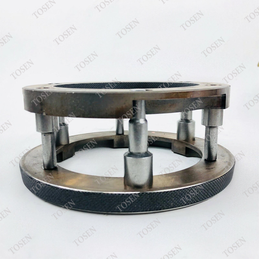
Then close the loop with your supplier. The record that made this install safe – kit reference, gearbox model, position, contents – is the same record that makes your next order correct. The product listing for the K3492 Synchronizer Kit for Eaton Fuller shows the kit reference, its earlier K-2446 reference and the ordering scope, so you can confirm the reference against the listing before the next teardown starts.
For other synchronizer positions, the transmission parts category carries the wider synchronizer range, and a supplier who can answer what exactly is in this kit in one message is the one worth re-ordering from.
Frequently Asked Questions
Can I install the synchronizer kit with the transmission still in the truck?
On some Fuller models, yes. Eaton documents an in-chassis path for the auxiliary section: drain the oil, disconnect the air line and wiring, unbolt the auxiliary case and jack the section out on a removal jack. Check your model's service manual for that option before committing to a full removal.
Do I have to replace the sliding clutch when I install a kit?
Only if the kit's scope includes it. The parts books show kit families side by side — for example, K-3492 covers the low-range large-pin position, while K-3494 is a replacement kit that includes the sliding clutch. Match the kit scope to the wear you found at teardown rather than assuming either way.
What do I do if the springs fall out during countershaft installation?
Stop the countershaft work, re-seat the springs in the high-range ring bores and re-run the seating steps, then continue. Eaton's manuals warn this happens because the driving force on the bearings can slide the direct ring off its pins — it is a recoverable interruption, not a damaged assembly.
Are all the synchronizer rings in my gearbox the same?
No. Within one synchronized gearbox, rings differ by position in both coating and size. In the light-duty synchromesh manuals, the 1st to 4th speed rings are EFM II coated while the 5th ring is not, and the reverse ring is coated but smaller. A ring that fits is not necessarily the ring that belongs.
Can I reuse the old synchronizer rings if they look serviceable?
Eaton's guidance is to replace damaged synchronizer rings rather than rework them, and a rebuild is the economical moment to fit new friction surfaces. If you are weighing reuse, judge wear against the inspection criteria in your model's manual — our synchronizer ring wear guide covers how to read a ring at teardown.
Which manual should I follow for exact torque values?
The Eaton service manual for your specific transmission model — this guide quotes the sequence and the rules that transfer across Fuller families, but torque values, seal positions and model-specific additions differ family to family. The manuals referenced here are the Fuller Advantage (TRSM0980), the heavy-duty RT-series books (TRSM0415/0507) and the synchromesh manuals (TRSM2105, FSO-2405).
Install With the Checklist, Not From Memory
The sequence in this guide is the one Eaton's own manuals document, and every rule in it is attached to a failure with a name — springs lost, gears slipping out, a section destroyed at first run. Work it in order: verify the kit against the position before the first bolt moves, assemble the sliding clutch and rings exactly as the steps lay out, respect the orientation and lubrication rules for your gearbox family, time the countershafts, and run the verification pass before the unit leaves the bench. Print the two checklists and keep them at the bench — they are the short version of everything above.
Before your next synchronizer job, confirm the kit reference, its supersession and the contents on the TOSEN AUTO K3492 synchronizer kit page, or browse the transmission-parts category for other positions — then order with the gearbox model and position in the enquiry.